Obstruction handling and dissolve shader techniques in Trifox
Hi, I’m Brecht Lecluyse, one of the developers at Glowfish Interactive that is currently working on Trifox.
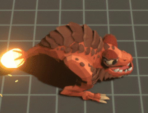
Trifox is a top-down twin stick action adventure game set in a unique and colorful world, inspired by classic platform games.
In Trifox you play as a multi-talented fox on a quest to restore and return peace to his recently invaded and plundered home.
Mix and match between three different and unique play styles, fight your way through swarms of enemies, engage in thrilling boss fights and overcome exciting environmental challenges as you discover that there is more to your quest than meets the eye….
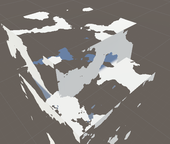
Where’s my character?
Defining the problem
One of the first challenges we faced during development was keeping the main character in view using the top down camera while at the same time maintaining the sense of being present in a full 3D environment. In other words, how do we deal with objects obstructing our view of the main character? Do we avoid them? Do we hide them? And if so, how do we hide them in a visually pleasing and smooth manner that fits with the style of the game? How can we maintain a sense of space without hindering gameplay?
This is a very common problem in games that share a similar camera setup like the one used in Trifox. So before we started implementing our own solutions we had a look at some tried and tested approaches of dealing with the issue we were facing.
The birds eye view
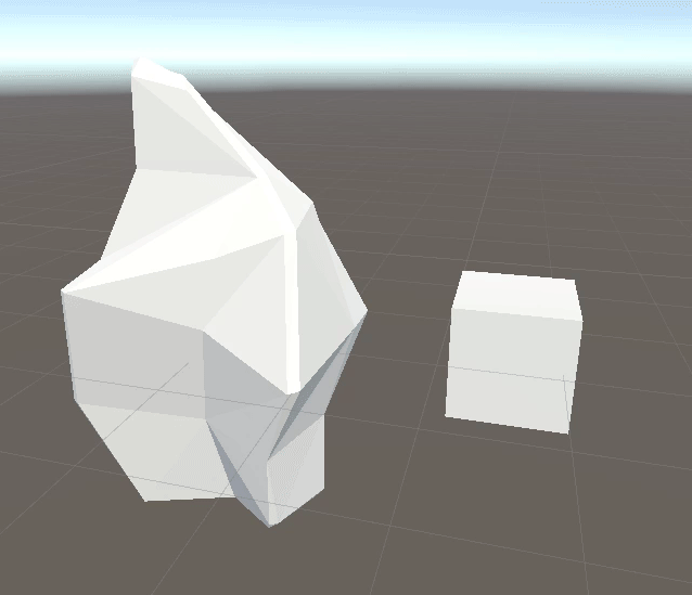
The first solution is to create the levels in such a way that it is impossible to have a large obstruction between the player and the camera. This means that most areas will need to be rather open and large, walls and obstructions need to be kept as low as possible or even avoided and the camera needs to be positioned at a substantial distance from the player, preferably looking as straight down as possible. This approach works well for games that are “Arcade”-like in nature or that have a more traditional top down RPG setup. In our case however, the large distance between your point of view and the character results in players feeling less attached to our hero. It also made the environments feel a lot more artificial and out of touch with the gameplay, feel and visual style that we are going for.
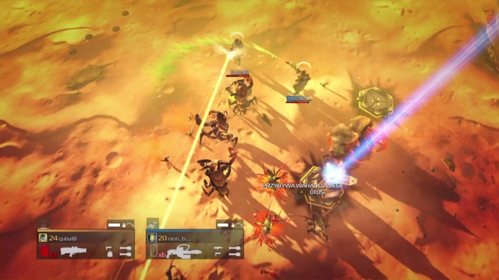
Birds eye view camera example: Helldivers by Arrow Head Game Studios
Slice and dice / popping the lid
The next solution involves cutting up the environment. Think of the level as being a multi layered cake. The player can only view one layer at the time based on where the camera is focused on.
When standing outside of a building you can see the building’s roof but once inside, the entire ceiling and upper floors are removed and all that remains is a cut-out view of the current floor and its walls. In most cases there is no roof to begin with as a way to avoid additional setup work. This gives the player a nice feeling of entering a building/area and allows for more complex level design with an increased sense of space. The camera still needs to be positioned at a fair distance with a direct angle looking downwards, but because we can hide/unhide obstructions we have a lot more freedom with the ways we can construct our environment.
Taking this approach further we can also hide walls and various other objects, should they obstruct our view, allowing for much lower camera angles and a closer view of the player’s character.
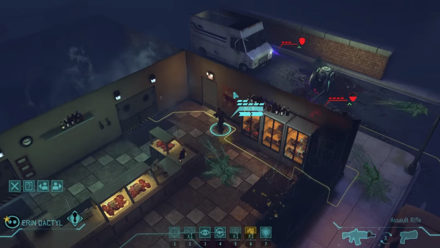
Popping The Lid camera example: XCom:Enemy Unknown by Firaxis Games
The only downside is that this kind of obstruction handling can often feel very harsh and artificial. This can be softened by having the obstructions fade out of view using a transparent material but in general we want to stay away from those as much as possible to avoid overdraw performance issues and transparent overlays that fill the entire screen.
This approach was more in line with what we were after but still didn’t really feel right for our game.
A natural evolution
Having looked at the conventional solutions we still felt there was something missing. These approaches work well for a lot of games but for us they felt somewhat out of place for what we want to achieve.
So exactly what is it that we want to achieve?
- Obstructions should be removed in a smooth and natural feeling manner.
- Level designers should have control of what can be hidden so we can leave select obstructions in place that can still hinder our view and create an added sense of depth within the environment.
- The system should work no matter what the distance is between the character and the camera position.
- The obstruction handling should work from all angles.
- The player should still feel aware that there is something there, even if the object is being hidden.
- The setup work should be kept to a minimum.
The solution we ended up with is a hybrid of all the previous approaches with some extra flavour to handle the hiding of obstructions.
Obstructions partially dissolve as the player approaches them, making sure the your view remains unobstructed while at the same time clearly indicating that there is something there. That way claustrophobic spaces still feel claustrophobic and walls gradually dissolve out of view without the effect being too aggressive. It also means we can easily have multiple intersecting objects of all sizes and shapes and have them disappear in a unified manner without any additional setup work.
So how did we achieve this? That’s a question I get asked a lot. And to answer that question we will have a look at how you can easily create a great looking dissolve effect that can be used for all kinds of things within any game.
I will go over the thought process that we used to find the final solution for our problem, starting with a more in depth look (aka tutorial) at some commonly used shader techniques that can be used to have objects dissolve into thin air.
The Power of Shaders: Basic dissolve shader and World Space UVs
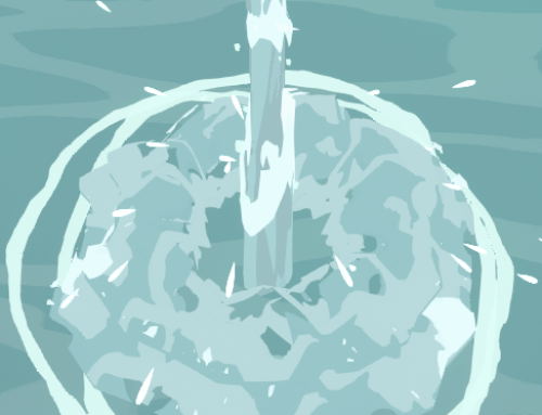
Noise based clipping
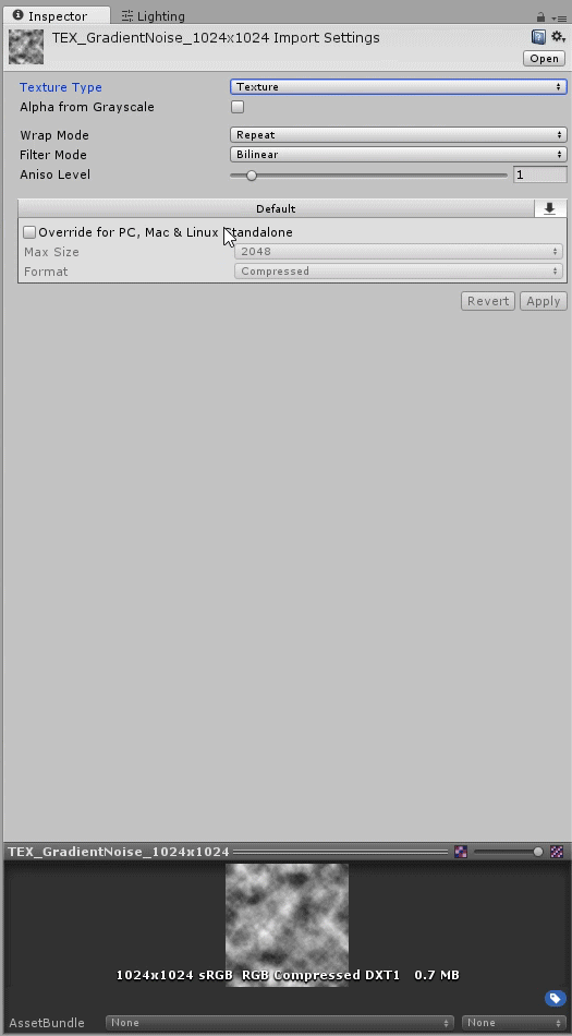
The simplest way to create a dissolve effect is by using a 2d noise texture and a shader technique called clipping.
The clip(value) function will do the following: everything with a value greater or equal to zero will be drawn on screen, anything with a value smaller than 0 will be invisible. Look at it as an on/off switch for your material.
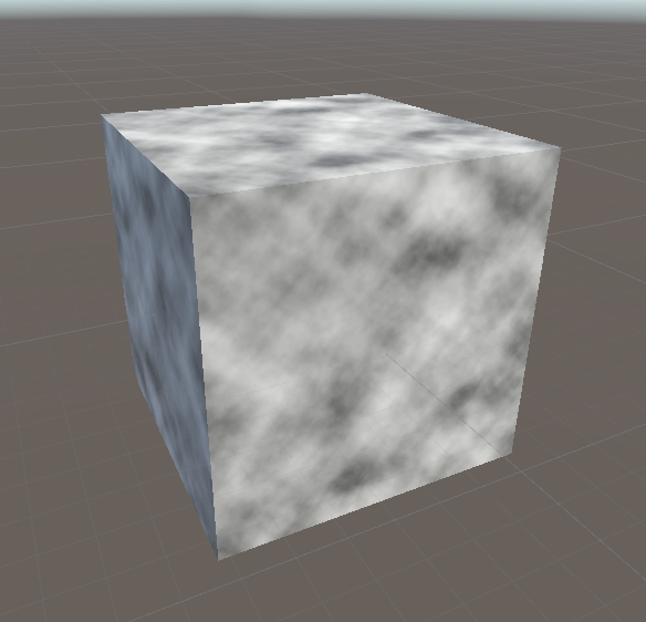
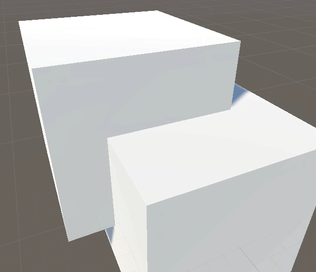
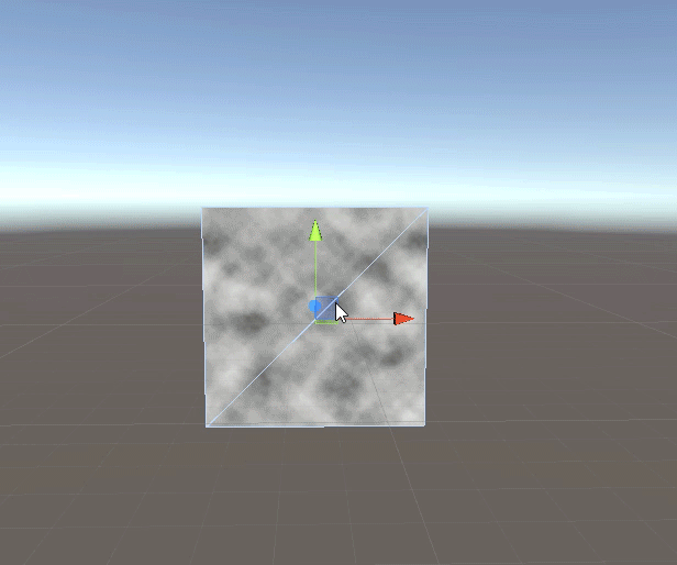
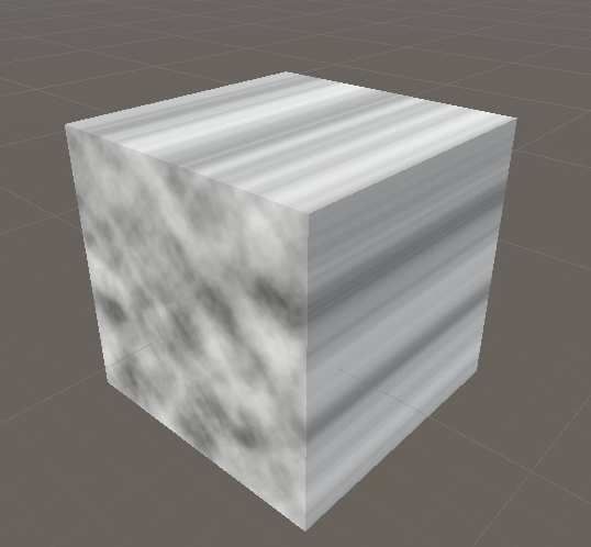
Here is a look at an example of such a noise texture and how it looks when applied to the default Unity cube.
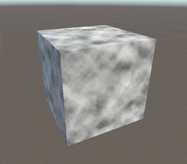
The next step is having the cube disappear gradually based on how this noise texture is applied to the object.
This is incredibly simple to achieve if we look back at how the clip shader function works and when looking at our gradient texture. All we have to do is take the grayscale value of our texture and subtract a value ranging from 0 to 1. This value can be seen as the dissolve percentage.
Implemented in a surface shader it looks as follows:
half gradient = tex2D(_MainTex, IN.uv_MainTex).r;
clip(gradient- _DissolvePercentage);
Shader "Custom/SHADER_blog_Dissolve_Texture"
{
	Properties{
		_Color("Color", Color) = (1,1,1,1)
		_MainTex("Albedo (RGB)", 2D) = "white" {}
		_Glossiness("Smoothness", Range(0,1)) = 0.5
		_Metallic("Metallic", Range(0,1)) = 0.0

		_DissolvePercentage("DissolvePercentage", Range(0,1)) = 0.0
		_ShowTexture("ShowTexture", Range(0,1)) = 0.0
	}
		SubShader{
		Tags{ "RenderType" = "Opaque" }
		LOD 200

		CGPROGRAM
		// Physically based Standard lighting model, and enable shadows on all light types
		#pragma surface surf Standard fullforwardshadows

				// Use shader model 3.0 target, to get nicer looking lighting
		#pragma target 3.0

		sampler2D _MainTex;

	struct Input
	{
		float2 uv_MainTex;
	};

	half _Glossiness;
	half _Metallic;
	half _DissolvePercentage;
	half _ShowTexture;
	fixed4 _Color;

	void surf(Input IN, inout SurfaceOutputStandard o)
	{
		// Albedo comes from a texture tinted by color
		half gradient = tex2D(_MainTex, IN.uv_MainTex).r;
		clip(gradient- _DissolvePercentage);

		fixed4 c = lerp(1, gradient, _ShowTexture) * _Color;
		o.Albedo = c.rgb;

		// Metallic and smoothness come from slider variables
		o.Metallic = _Metallic;
		o.Smoothness = _Glossiness;
		o.Alpha = c.a;
	}
	ENDCG
	}
		FallBack "Diffuse"
}
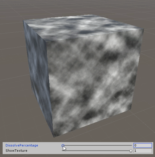
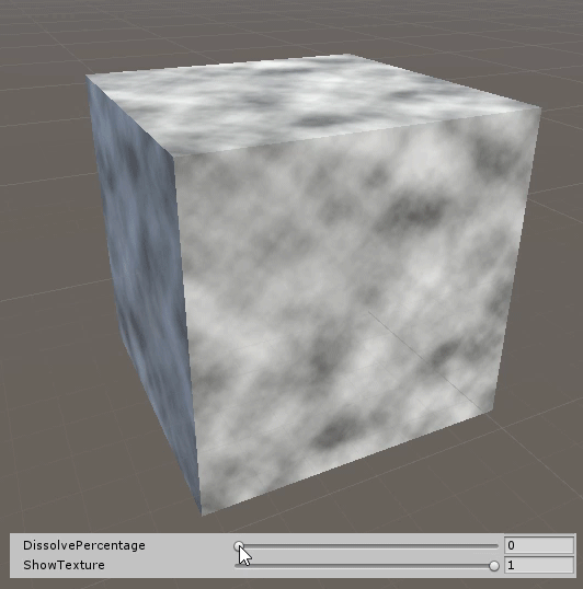
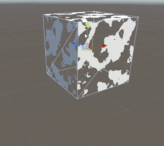
Increasing the _DissolvePercentage parameter will result in the following effect.
And that’s it. The basic technique to create a dissolve effect. Easy right?
Now if you were to try this yourself you might end up with a slightly different result. The noise texture will probably look a lot darker and when increasing the dissolve percentage parameter you might notice that the object will be fully dissolved at around 75% instead of 100%.
Not really what we expect as the texture has a range that perfectly transitions from 0 (black) to 1 (white). Then why is it doing this?
This is because of the gamma correction that is applied to textures when they are imported into the engine. In this case we want to use the texture as a linear data texture, meaning we want to use the rgba values as a way to store information instead of a color value.
Therefore we want to make sure this information remains unaltered by the importing process.
This can be achieved by making a small adjustment to the texture import settings for this particular texture.
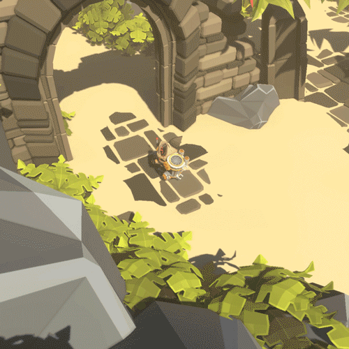
In the “Import Settings” window, set the texture type to “Advanced” and make sure the “Bypass sRGB Sampling” flag is enabled. In the animation below you can see the difference between having this setting enabled and disabled. This can be of great importance when dealing with more advanced shader effects that make use of data textures.
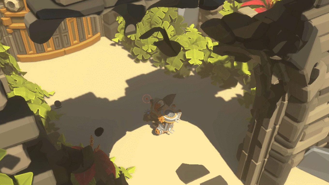
This works great for meshes that have an unwrap that takes the dissolve effect into account but what if that is not the case? And what about intersecting objects, can we create the illusion that they are in fact a single object?
Unless we unwrap each object with the dissolve texture in mind we will end up with a large mismatch between the different dissolving objects when placed next to each other. And what about scaled objects? We would need a different material for each scale in order to keep the noise detail consistent. Clearly this is a less than ideal solution that takes a lot of setup work and back and forth to get right. Up next: replacing the manual unwrap with a procedural world space unwrap.
World Space UVs
Usually textures are mapped to the surfaces of a mesh based on the UV coördinates that were defined during the mesh creation process. But instead of using these coördinates we want to use a new set of coördinates based on where the surface is located within the environment.
By adding Unity’s build in shader input variable “worldPos” (https://docs.unity3d.com/Manual/SL-SurfaceShaders.html) we gain access to this information within our shader.
As an example, here you can see the result of the following code adjustment on a quad moving in the XY space. We use the x and y world space coördinates that are stored in the red and green channel of the “worldPos” input variable instead of the unwrap UV coördinates that were stored in the mesh.
Original:
half gradient = tex2D(_MainTex, IN.uv_MainTex).r;
Unwrap UVs replaced with world space coördinates:
half gradient = tex2D(_MainTex, IN.worldPos.rg).r;
This is a common shader technique that can be used for all kinds of fun procedural texturing techniques. You could, for example, use this to automatically create water damage on surfaces that are positioned below a certain height.
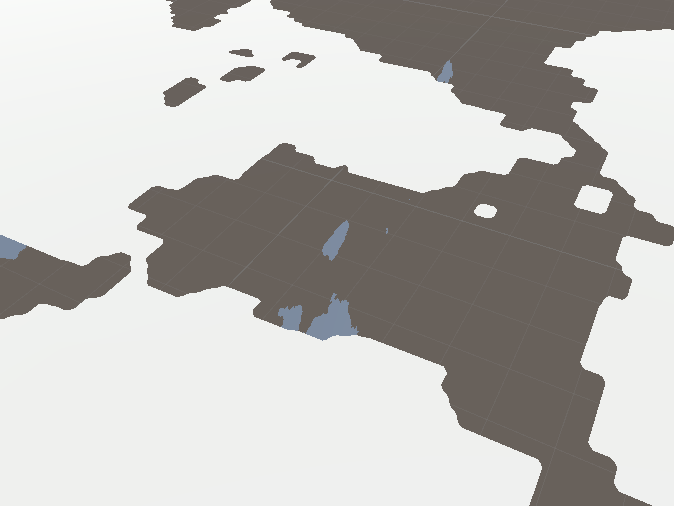
Applying the adjusted shader to our cube again reveals that the world space texture technique needs some additional work for it to be usable for the dissolving effect. Currently the procedural unwrap only works well within one 3d plane, in this case the XY plane as those are the coordinates that we used to replace our UVs with.
Using some vector math we can calculate a UV set that works well for all surfaces no matter how they are oriented within the world. The result is a texture applied to a mesh that stays consistent between different meshes regardless of orientation, scale or position.
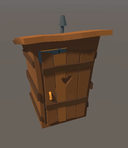
Applied to a final game asset, the result looks as as follows:
For most situations this would be more than enough, but we didn’t stop here.
As you may have noticed in the images above, using this kind of noise can often generate nasty dissolve edges. Additionally, because we are using a texture, it is impossible to get close to the object without clearly noticing the pixelated transitions.
We also cannot guarantee a nice continuation of the noise texture across large surface angle differences and between intersecting objects.
To Be Continued
That wraps it up for part 1. In part 2 I will go over how we took care of the issues caused by the use of a noise texture, improved the overall quality of the dissolve effect and how we use this simple technique throughout Trifox to create all kinds of fun visual effects (including the dynamic camera obstruction handling) and even some cool gameplay mechanics.
Until next time!
-Brecht
Update
Trifox is now available for Steam Wishlisting!